Pete,
petercoll wrote:Can someone point me in the direction of some instructions on how to do DIY tracking / wheel alignment please
I frequently, every couple of races, completely check the suspension of my race Fury using a collection of devices that I've made myself. I am a wee bit anal about all this though as it's makes a huge difference for a race car. (For example, just try pushing your car around on full lock and compare it to how easy it is to push with the wheels pointing straight ahead.)
I check the wheel camber with this device:

This is just a spirit level with a couple of M6 bolts tapped into it. Assuming the car's on a level surface then I adjust the little bolts, which are pressed against the wheel rim, so that the spirit level is vertical. I then measure the length of the bolts with a vernier caliper (a proper one, not one of those nasty electronic ones) and do a little bit of trigonometry to come up with the camber angle. In fact, I did all that in advance and the numbers are written on a bit of masking tape on the spirit level. An alternative is to buy an inclinometer like
this one and read the angle directly. (Although, you'll have to set the zero position on the gauge first.) If you like that idea, they're on ebay for around £20, just
search for "inclinometer".
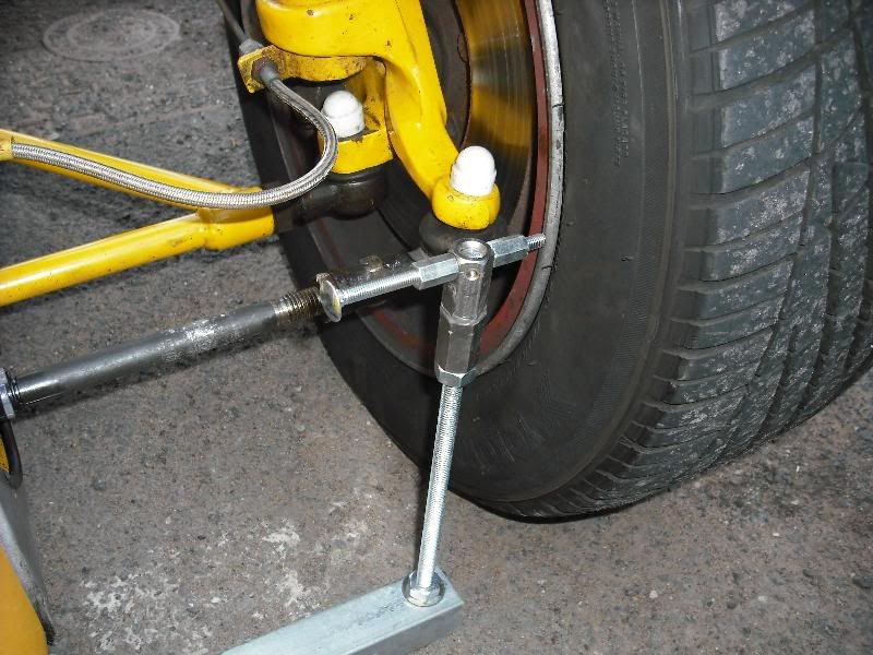
As for tracking, I made this device:

That's a bit hard to see, so here's one of the ends a bit closer up:

Essentially, it's a sort of giant "C" shape. Because of of the "fingers" on the end you can arrange to get this positioned so as touch the outer side of the wheel rim on both the left and right hand side of the car. So, for example, if I want to set the front wheels to toe out a bit, I:
- insert the thing at the front of the front wheels,
- adjust it so that the "fingers" just touch the rim
- move it to the rear of the front wheels and
- check that the fingers don't quite touch the rear of the wheel rims by the amount I'm aiming for.
Not as convenient as using a laser alignment gauge but a lot cheaper. If you're aiming for toe-in then you'd start at the rear of the wheel rims.
I also check that the rear wheels (my car's an IRS one) are pointing straight with respect to the front wheels. Unfortunately, I don't have a photo of the device here but it's just a lump of 1" square ally extrusion that fits snugly into the wheel rim. Attached to this (by some duct tape!) is a small laser pointer I bought from Maplins. I've also got a little cardboard gauge that I attach to the front wheel hub with something sticky, blutack works well! I put the ally in the rear wheel and read off the gauge how far away from the front wheel hub the laser passes, and then do the same on the other side of the car. Ideally, the measurements will be the same. The track on the Fury is a little wider at the rear than at the front; this wouldn't work if that wasn't the case.
Note that all this is the laser equivalent of the traditional chassis "stringing". In fact, if you seach for "laser string" on the 'net you'll find a lot of devices that do this for you. Mine's just cheaper!
The order that things are done in is quite important. I do this:
- check the ride height front and rear
- check the camber front and rear
- adjust the front toe
- measure the rear toe and the longitudinal alignment. If I'm clever then I can adjust them both in one go, as I use the rear tracking adjustment for both.
- Finally, I do the whole lot all over again to check it's right, and worry if I don't get the same measurements for everything.
I've also got a bump steer gauge that I made which comes out occasionally. If you want details, ask and I'll dig the photos out of that too.
It takes a Saturday to do, really...
HTH,
Tim
(Edited to fix the photo URLs. If they disappear again email/pm me and I'll sort it.)