Page 3 of 4

Re: Data Logger DL1 Mk2, PCB soldering

Posted: Tue Apr 13, 2021 11:06 am
by peter030371
pigeondave wrote:Ohhh exciting!!!


lockdown must be really getting to you is half a dozen 1k resistors is exciting :lol:

Re: Data Logger DL1 Mk2, PCB soldering

Posted: Tue Apr 13, 2021 2:08 pm
by pigeondave
peter030371 wrote:
pigeondave wrote:Ohhh exciting!!!


lockdown must be really getting to you is half a dozen 1k resistors is exciting :lol:


Anything is better than work!
But yeah its been slow :D

Re: Data Logger DL1 Mk2, PCB soldering

Posted: Thu Apr 15, 2021 2:20 pm
by pigeondave
@peter030371
Eagles fly west over Moscow

Package received, many thanks comrade. :D

Re: Data Logger DL1 Mk2, PCB soldering

Posted: Thu Apr 15, 2021 2:24 pm
by peter030371
pigeondave wrote:@peter030371
Eagles fly west over Moscow

Package received, many thanks comrade. :D


:lol: I read that first line and thought WTF is he on about...took a few seconds for the penny to drop :D

Re: Data Logger DL1 Mk2, PCB soldering

Posted: Fri Apr 16, 2021 7:44 pm
by adithorp
peter030371 wrote:
:lol: I read that first line and thought WTF is he on about... :D

I wonder that quite often :lol:

Update Data Logger DL1 Mk2

Posted: Fri Apr 30, 2021 7:31 pm
by pigeondave
You all probably wondering how can I be hanging this out for so long.
I'll use work as an excuse. We've been busy, we're always busy.

Anyhow I was thinking how to map the voltage to a temperature. My first thought was to get a new battery for the laptop so I can sit in the car with the logger on, have it live to the lappy, dunk the temp sender into a hot cup of tea with a thermometer also in the cup, and log the temp to the voltage.
At the end I'd get a cold cup of tea so it wouldn't be all bad. (cold tea better than no tea)

I then thought I'd do some digging.

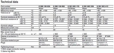
Looking at the table below it appeared that my 0 281 002 412 had very similar characteristics to the 0 281 002 170, which is also known as the NTC M12-H in motorsport circles.

Image

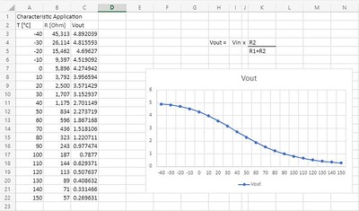
I found the data sheet for this and got about doing some more digging (electrics are not my strength). I found some online help so I could turn my resistance into a voltage. The pull up resister is just a voltage divider, so with a bit of excel and GCSE physics I got....

Image

The R-T software has the ability to take data and provide you with the equation (excel does this too) so I'm now thinking I just need to solder up the wires and I could possibly be good to go.

Fitting this will involve doing an oil change, who knows how long that could take...

Question is, do I cut the ring off the sensor and replace it with a ford rubber sump plug bit, or leave the ring on and nip it up as normal??

Re: Data Logger DL1 Mk2, PCB soldering

Posted: Mon May 03, 2021 5:45 pm
by adithorp
The ford rubber dump plug gasket requires a groove in the plug to stop it squishing out do I'd stick to the (ally') washer on the sensor

It Works! Data Logger DL1 Mk2

Posted: Fri May 14, 2021 12:00 am
by pigeondave
I've lashed it together and it works.

I stuck the temp probe in my pocket hence the initial drop, then tried to warm it with my hand, then stuck it under my arm.

This is a plot against time (not distance)

Image

Things to watch out for. They say the connector type is 3.5mm pitch lever connectors, wire sizes 16-28AWG, 0.32-1.3mm diameter.

1.5mm wire doesn't fit in the connector, and with my fat fingers 1.0mm wont fit either. You'd think I'd be good at getting fat things into tight holes, but it appears not. I lashed something up with 0.5mm wire, as I had used the 1.5mm in the Bosch sensor connector thinking it would make for a waterproof connection. 0.5mm was a git to strip with my wire strippers though. I think the end game will be to use 0.75mm. My motto, go as fat as you dare. ;)

Also I think my battery has run out, the internal time seems to have been reset to 2004, bit of a bugger. I have read of people soldering in a battery holder so that it's easier to change out. But one step at a time.

I'd like to thank obfripper for his advice and a special thanks to peter030371 for the resistors and offers to help.

Re: Sensor help please

Posted: Wed Nov 10, 2021 2:19 pm
by pigeondave
Hi All,

I've been slowly plodding on and have bought one of these
https://www.mouser.co.uk/datasheet/2/65 ... 216826.pdf

I have one issue and one potential issue.
1. I can't seem to find any data to work out how the output is related to Pascals.
2. Looking at the Technical data on sheet 2 can I plug this straight into the DL1? I think I can as the output is volts, but the Ohms bit confuses me.

Thanks

Dave

Re: Data Logger DL1 Mk2, PCB soldering

Posted: Wed Nov 17, 2021 10:52 pm
by obfripper
1 inch H2O is 249 pascals, the data sheet is not clear, but it's likely to be a linear relationship, with 0.25v at minimum pressure difference, and 4.0v at maximum pressure difference.
The model number should give the applicable range, as there appear to be both +/- pressure and + only pressure versions.

The input impedance is unlikely to affect it's use with the dl1, you should be able to use any of the 5v analogue inputs for this sensors output, and power it from the sensor 5v supply.

Dave